
When working on our Audi R8 project, one of the things we wanted to update was the head unit. We soon learned that there was no practical off the shelf solution to fit into the car in right-hand drive. There is a limited choice of bezel available in RHD and it is difficult to confirm the correct wiring harness for the car. We are going to document our installation to save you some time. We are not audio professionals and may get some information wrong, so please let me know in the comments if you have improvement ideas.
Headunit Choice – Eonon GA2178
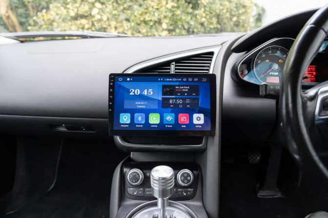
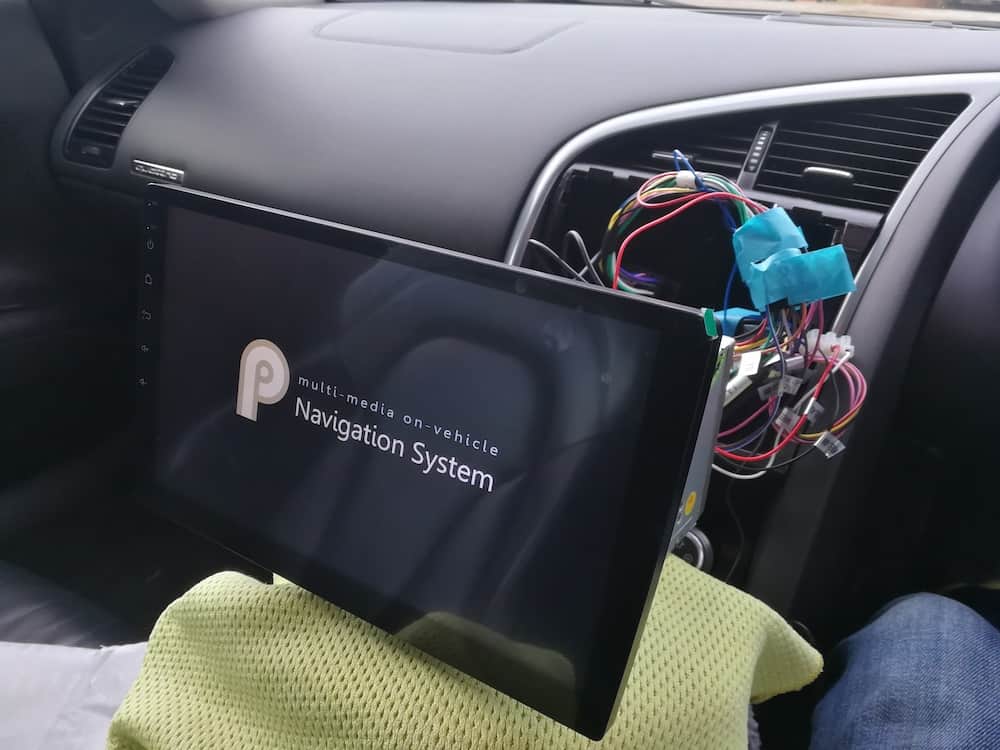
We decided on a floating screen because once you remove the original head unit and control buttons below, simply fitting a double din unit does look a little plain. We went for the Android Eonon GA2178 unit.
Equipment List
Here is a list of all the equipment that we purchased/used for this installation:
Double Din 180x113mm Replacement Cage Kit For Car Radio Head Unit – £16.99
Autoleads ControlPro 2 Steering Wheel Interface CP2 VAG52 – £59.99
PC5-137 Audi Symphony BOSE Car Radio Amplified Fakra Aerial DIN Adaptor – £10.99
Eonon GA2178 – £294.00
Optional Extras
CarPlay Dongle A0585 – £79.99
3.5m Female Socket (ebay) £2.09
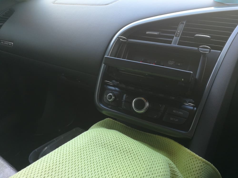
Factory Head Unit Removal
To remove the original head unit, you will need four Audi head unit removal keys. It helps to have the screen folded down to allow you to get more grip on the head unit before pulling it out. Remember to remove your CDs from the CD changer before removing the unit.
3D Printed Bezel
So it all starts with the bezel. A right-hand-drive bezel is very hard to come by and if you do they cost about £500. The second option we have is to 3D print one. I found the design already done here by ZaOS. I got the RHD version printed and it worked well in a UK spec car. If you are unable to source a 3D printer yourself, then there are many places that will 3D print for you such as SGD.
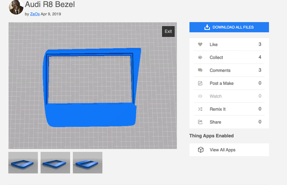
The bezel itself fits really well. You might wish to paint or wrap the bezel depending on what unit you are going for. I chose to wrap the bezel. This was a difficult undertaking for me, but I knew the bezel would be hidden behind the screen, so it was no big deal.
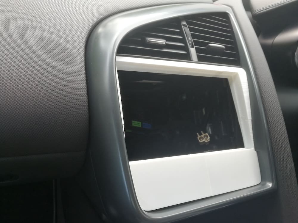
Once the bezel goes into place, another thing to consider is that it isn’t secured to the car, so the head unit can be easily removed. It’s not a problem, just something to think about.
The Double DIN Cage
You are going to need a cage that fits inside the bezel. I chose the DFPK-113 Double Din 180x113mm. With dimensions – 180x113mm. It wasn’t a perfect fit but it worked.
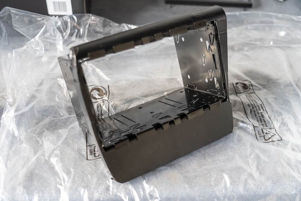
It held the head unit perfectly but didn’t hold the bezel tight. Also, I made the mistake of securing the cage to the bezel before fitting the bezel to the car. This meant that I wasn’t able to perfectly align the bezel in the car as the cage prevented me. If I did it again, I would fit the bezel first, then instal the cage. On the plus side, the cage has a nice surround that hides where it meets the bezel.
Autoleads ControlPro 2 Steering Wheel Interface CP2 VAG52
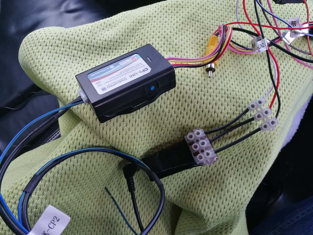
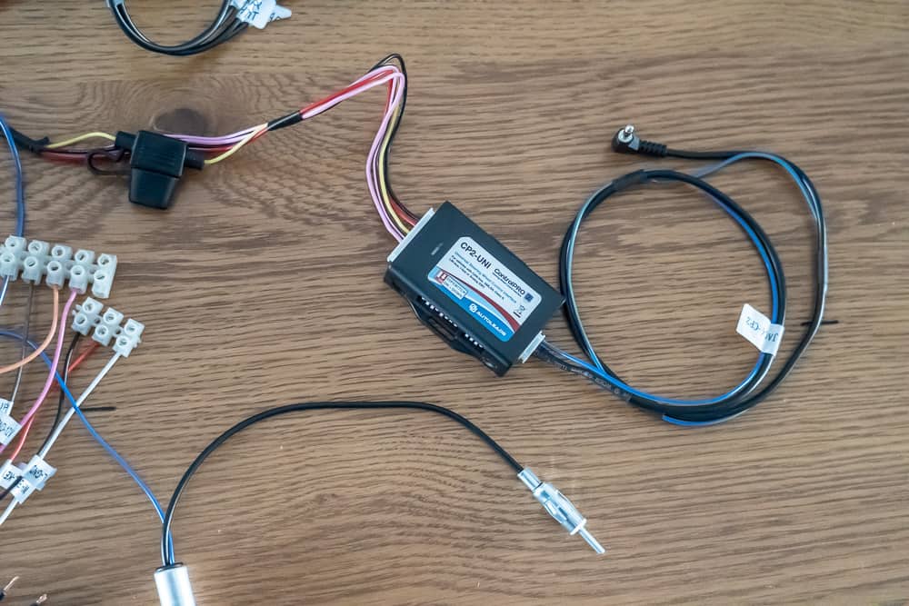
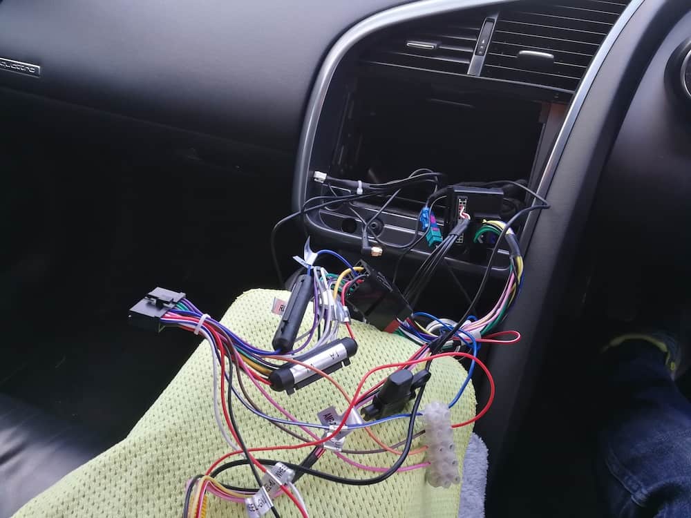
There was little information online about adaptors for use with our 2007 Audi R8. I opted for this Autoleads ControlPro 2 Steering Wheel Interface CP2 VAG52 in the end, as it promises to keep the steering controls. It uses phonos to communicate the sound as the car doesn’t have the wiring block in the quad lock system as I expected. Also the steering controls worked, no problem at all.
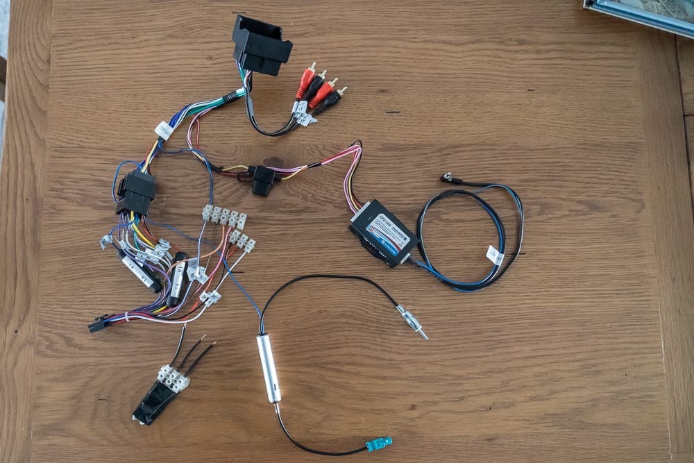
You will need to make sure that you connect the ‘amp on’ cable to the car wires so that it knows to turn the amp on. Otherwise, you will have no sound.
As you can see, a lot of wires need to go into the car. I added a connector block to the loose wires to help manage the wire connections.
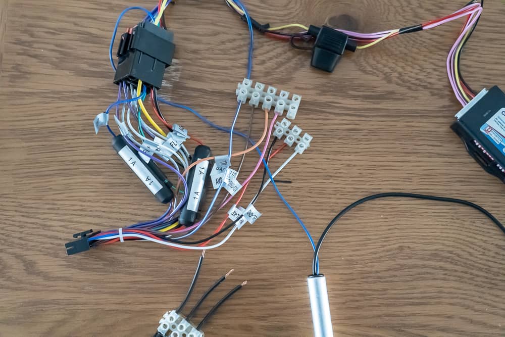
The steering wheel controls will work well for most premium aftermarket head units. They will need to have a 3.5mm jack to receive the information. The Android-based head unit we fitted here did not include the 3.5mm jack and had just three wires. I bought a 3.5mm female jack from eBay and soldered three wires from the jack and then fed them directly into a connector block. This meant that I could keep the cable on the VAG52 and use it to plug and play. The Android head unit could easily decode the signal, even when using this method.
On the VAG52 you will need to follow the instructions to set it up for an Audi R8 using the dip switches. This was very straightforward. There are further dip switches for the type of head unit you are using. For our installation, we set it to Alpine mode and it worked fine.
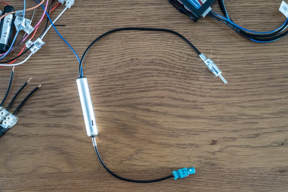
PC5-137 Audi Symphony BOSE Car Radio Amplified Fakra Aerial DIN Adaptor
I’m sure there are many options for this cable but we chose the PC5-137 to Fakra aerial adaptor. It is a simple plug and play model. It also comes with a small push adaptor that you need to plug into the car harness to turn the signal booster on.
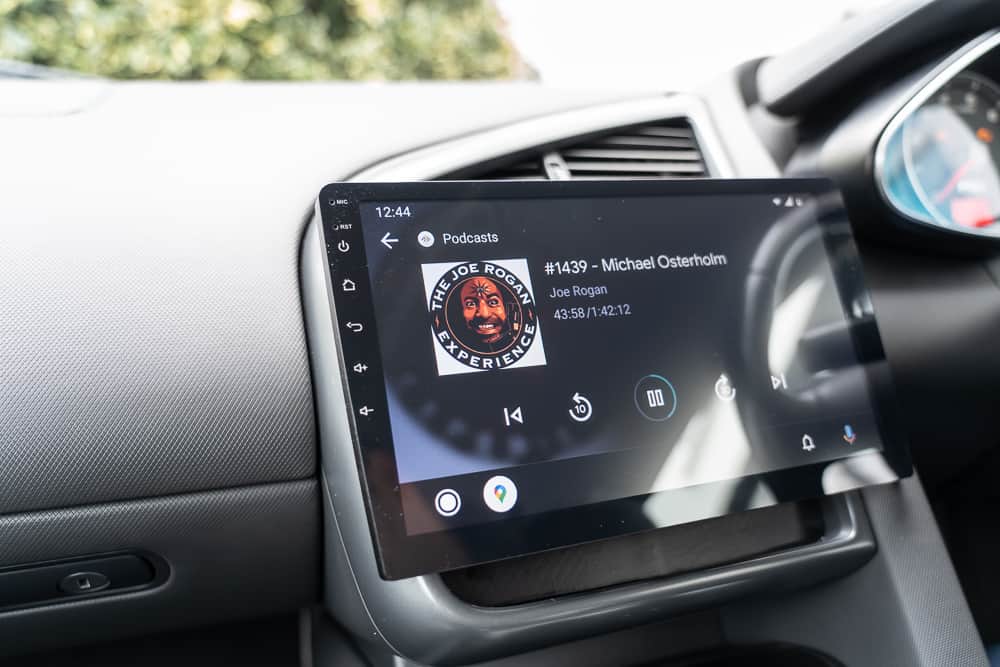
Eonon GA2178
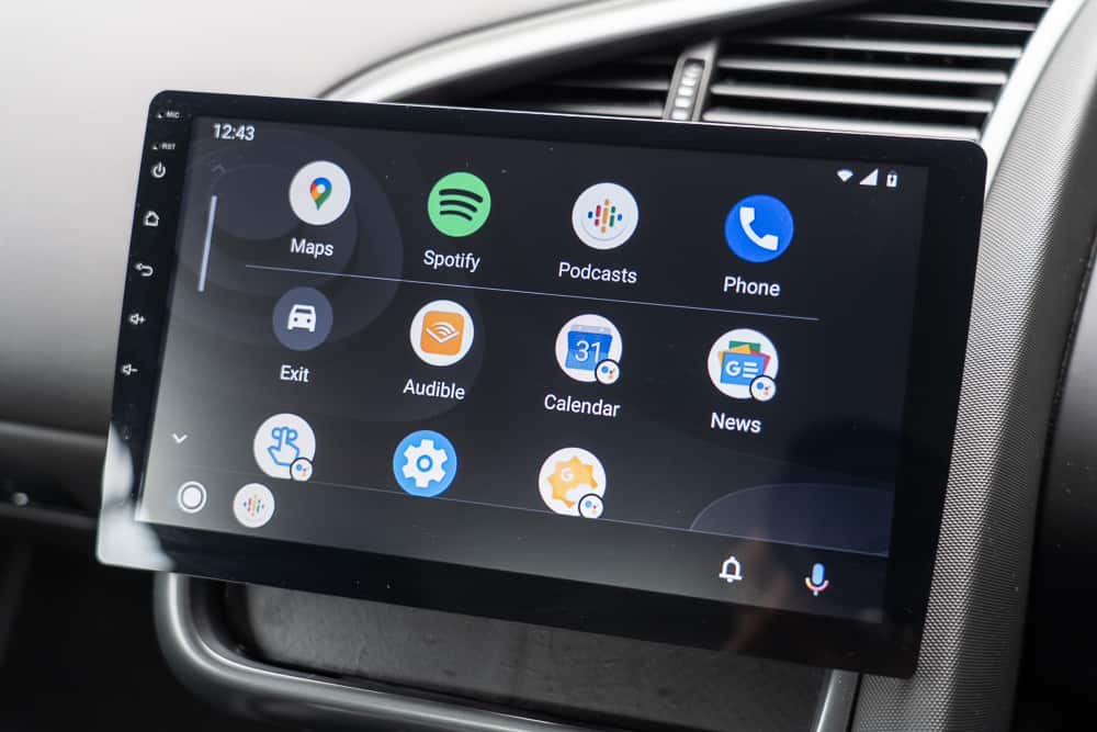
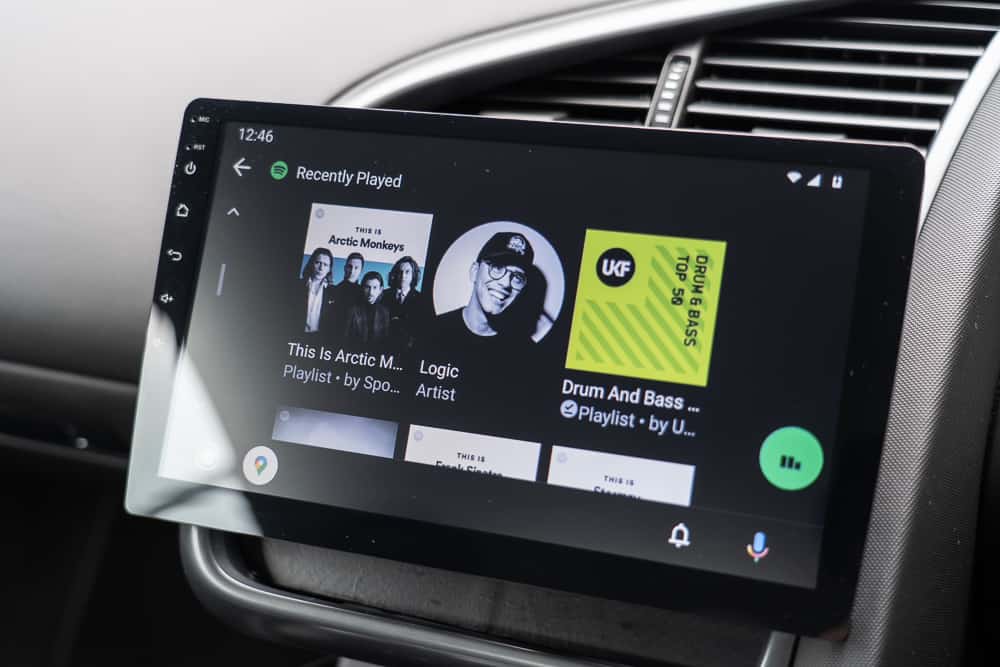
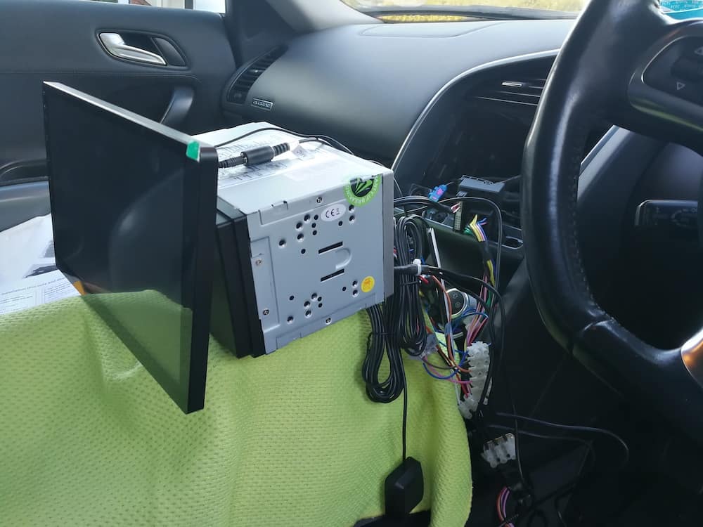
So we chose the Eonon GA2178 that came with a dashcam, rearview cam and OBD dongle. In short, it worked out really well. The large screen looks premium and has a good resolution. It also allows you to use Apple CarPlay and Android Auto, with the addition of the USB dongle, which is perfect!
With the bezel and cage fitted to the car and the wiring harness configured and plugged in, we could start to wire everything together for a test.
I protected the centre console of the car with some clothes and used upside-down Tupperware to cover the gearstick to free up my hands by resting the head unit on there.
There are several different wires that need to be plugged into the car. So let’s run through them.
GPS Antenna: You need to make sure you can get this as high into the dashboard as possible and away from metal parts in the car to ensure it gets a good signal.
WIFI Antenna: The same thing goes for wifi. My original location just behind the head unit got poor signal.
ISO Port: This is where the bulk of the cables connect to the car’s wiring harness. It is easy to plug in.
USB Ports: You have three USB ports/cables. Your CarPlay dongle will be plugged into one, the second will be used for the dashcam and the third for a USB stick for the dashcam to link to.
Audio Phonos: From the wiring harness you need to plug in the front and rear speakers. They will be a bit loose and the cables are short, so make sure they don’t slip.
Steering Wheel controls: As mentioned above, I used a female 3.5mm jack to manage these cables. But you could get the connectors on the harness and hard wire them. I think they can be fitted in any order and the head unit will decode them. Or maybe I just got lucky first time!
External mic: Run the mic cable from the back of the head unit as close as you can to the driver. I ran the cable up the A-pillar and it worked out well.
Amp Control: It is essential to connect the amp control cable from the head unit through to the wiring harness, otherwise the car’s amp will not turn on.
Optional:
Illumination: If you want to the head unit display to be affected by your car’s headlight status, then you must connect this to the car
Reverse control: If you are using the reverse cam, this cable is used to bring the camera feed on screen. You must also connect the rear camera input.
Power Up And Test
Before feeding all the cables into the car, I would make sure that you have tested everything as much as you can. Check all the functionality – speaker channels, GPS signal, wifi signal, radio signal, steering wheel controls etc.
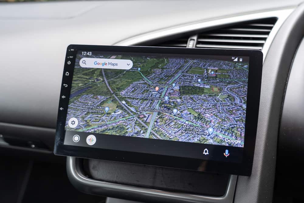
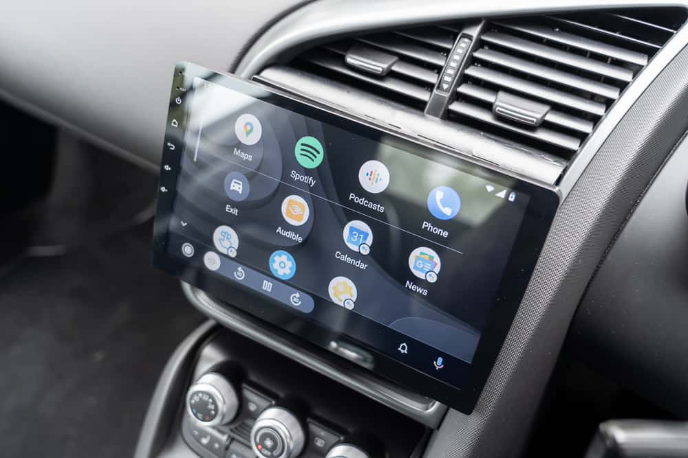
Finished
Here is how it looks once complete:
References
RNS-E Pin Out Information
: Speaker Connecter (front passive speakers)
1 – N.C. (NC = Not Connected)
2 – Right Front (+) (ok)
3 – Left Front (+) (ok)
4 – N.C.
5 – N.C.
6 – Right Front (-) (ok)
7 – Left Front (-) (ok)
B. EXT Control Connector (CD Changer, PhatBox, OEM SAT tuner, Dension IceLink etc.)
1 – Most Ring break (Used for MOST network diagnostics to “break” the MOST ring; This will never be used in any RNS-E install to date)
2 – CDC-NF GND (audio ground for CD changer; this should NOT be connected to any chassis ground source)
3 – V-Signal (analog speed signal or GALA in B5, C5 and D2 chassis)
4 – U14R-2 (Constant power source for CD changer, phatbox, oem or aftermarket ipod interface etc)
5 – K-Line (K-line diagnostic; needed to configure your RNS-E via a VAGCOM)
6 – CDC-Data out (ok)
7 – *BOSE Pin (used if you have a Bose system)
8 – CDC-NF L.IN (ok)
9 – CDC-NF R. IN (ok)
10 – U14 ST CDC (Ignition/accessory power for CD changer, phatbox, oem or aftermarket ipod interface etc)
11 – CDC -Data IN (ok)
12 – CDC- Data CLK (ok)
*The Bose pin was commonly found in the B6/B7 A4s, C5 A6 and D2 A8’s with a model year of 2002+. This should be connected to the bose pin in your factory harness. Per Lee Hicks (NSX Jr): This should be connected to ground if you have a BOSE system. I tried it both ways, and it sounds WAY better when grounded… obviously only if you have the BOSE system. By grounding, you tell the RNS to use a different audio equalization and processing before it sends out the signals to the amp.
C: EXT Control Connector (For Bose or Non-Bose Amp, telephone interface)
1 – **MIC IN (-) (Used for OEM Bluetooth kit when SDS is factory installed)
2 – *RFSL (Analog reverse signal)
3 – Line Out FL (front left audio signal)
4 – **MIC Out (-) (Used for OEM Bluetooth kit when SDS is factory installed)
5 – Line Out RL (rear left audio signal)
6 – TEL NF IN (-) (Telephone speaker negative input)
7 – **MIC IN (+) (Used for OEM Bluetooth kit when SDS is factory installed)
8 – Line Out GND (audio ground)
9 – Line Out FR (front rear audio signal)
10 – **MIC Out (+) (Used for OEM Bluetooth kit when SDS is factory installed)
11 – Line Out RR (rear right audio signal)
12 TEL NF IN (+) (Telephone speaker positive input)
*Reverse wire: C5 A6, B5 A4/S4 and D2 A8 use an analog signal for reverse. Most harnesses won’t have this connection available…so you will need to add a female pin/wire (part#000-979-009) and route it to reverse signal near the drivers’ side lower dash area (see www.nsxjr.com for location of reverse signal in a C5 A6).
**SDS (Speach Dialog System) will need to be factory installed (found in B7 A4/S4 for example) in order to take advantage of these mic in/out wires. If no SDS, then you will connect the mic wires directly between your OEM bluetooth kit and the BT mic that you install near your sunroof controls.
D: Power Connector
9 – CAN-H (CANbus High signal)
10 – CAN-L (CANbus Low signal)
11 – TEL-Mute (Telephone mute connection)
12 – Kl.31 (Primary ground connection)
13 – U14 ST DSP (Radio On) (Provides a switched ignition-out source to turn on rear amplifier (bose too) or “remote” lead for an aftermarket amp)
*14 – DWA-GND (Alarm ground)
15 – Kl.30 (Constant 12V power source)
16 – U14R-1 (N.C.)
32 Pin Connector: (A/V interface; Dietz 1417/1280/1215 and OEM TV Tuner)
1 – N.C.
2 – N.C.
3 – N.C.
4 – N.C.
5 – N.C.
6 – AUX-NF-IN Right
7 – N.C.
8 – N.C.
9 – N.C.
10 – N.C.
11 – N.C.
12 – N.C.
13 – NF-IN-Right
14 – SHIELD GND
15 – IN-Sync
16 – IN-G
17 – N.C.
18 – N.C.
19 – N.C.
20 – N.C.
21 – AUX-NF-GND
22 – AUX-NF-IN-Left
23 – N.C.
24 – N.C.
25 – N.C.
26 – N.C.
27 – N.C.
28 – NF-IN-GND
29 – NF-IN-Left
30 – RGBS-IN-GND
31 – IN-B
32 – IN-R